
The Track link along with the bush are often the most important components to measure during a machine audit. The links can be measured using 2 of the available tools: Ultrasonic Tool and the Depth Gauge.
Ultrasonic Tool
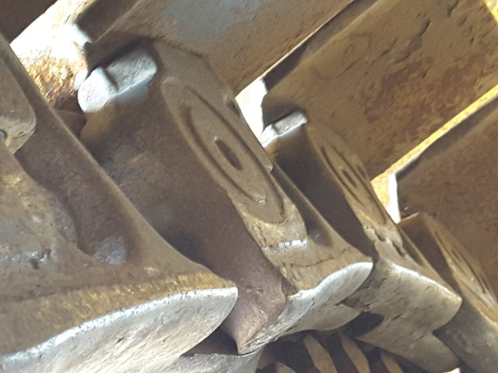
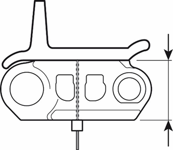
The Distance F is measured using the Ultrasonic Tool. A small amount of Gel is placed on the face of the probe and then placed on the rail surface.
A mistake can easily be made when measuring these components with the points of measure.
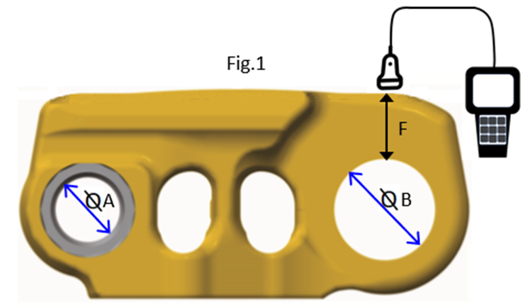
In the following Fig 2., the diameter of A which takes the Pin is less than diameter of B. which is where the bush is fitted.
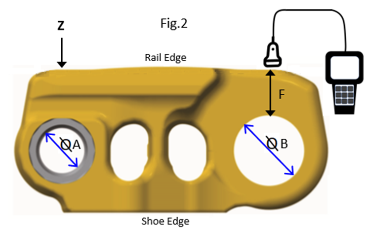

Measuring the Links with a depth gauge is relatively simple. The following diagram demonstrates the position of the tool for measuring
In the elevated sprocket dozers, it is common to take a measurement in the middle of the Link as in Fig 5 and then compare the difference between the measurement in Fig 4 and Fig 5 to determine the level of scalloping:
Signs and symptoms to be on the lookout for when examining the Track Links
All metal tells a story. During the machine audit, the wear patterns should be examined and analysed so as to prevent accelerated wear and early retirement of the metal.
Link Cracking – this could be caused by tight track, or wide shoes, high impact environment or link twisting. Cracking will reduce the life of the link; thus it would be good to check all the other links for these signs. If necessary, weld as a short-term solution, and try to identify the cause, but plan for replacement when possible. Link cracking might originate from corrosive environments such as Phosphates, coal or sulphur.
Side Rail Wear – this is where the rail is coming into constant contact with the roller flange causing wear on the side of the rail. This could be caused by: turning in one direction mostly, working on a side slope, track frame misalignment.
Link Scalloping – primary scalloping is typically caused by the idler carrying the load on elevated sprocket machines. The idler carries the load because the rear track rollers are not performing their task correctly due to worn bump pads under the rear bogies or worn track rollers. The machine balance should also be checked.
Link Spalling – this is characterised with large chunks of metal coming of the link and can be caused by high impact loads, excess loading caused by shoes being too wide, tight track or extra machine weight. The effect can be shortened link life and potential track snapping or separation in the field.
Oil Leaks – signs or oil leaking or having leaked can be found from the bushes on the outside of the link. This can be caused by damaged or worn seals, overheating track, pin and bush wear. Seals can be damaged through corrosive environments. Where there are oil leaks, check the other links for signs of the same, and perform a temperature test. Links leaking oil result in dry joints which will then overheat causing further damage. Plan for the chain repair quickly to avoid permanent damage.
TrackTreads Undercarriage Management System
The TrackTreads system enables inspectors in the field to measure undercarriage components with a mobile app with all the available tools, and record images and observations of potential symptoms identified which can be further reviewed after syncing the data to the web application. A detailed report can then be issued to the customers of the machines condition.
Contact us for further information of for a demonstration.