Pins and bushes can be one of the trickiest components to measure when performing a machine audit. Here are some tips and thoughts to help you.
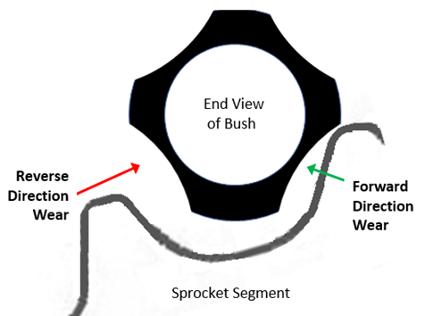
The Pin and bush on the undercarriage chain is subjected to wear from 2 directions depending on whether the machine is being operated in the forward direction or in reverse.
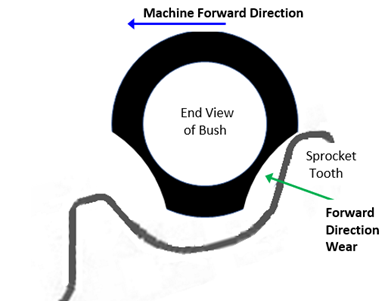
Note: The bush and sprocket configuration are specifically built for maximum load in the forward direction.
Reverse Direction, the sprocket tooth will engage the front lower section of the bush face
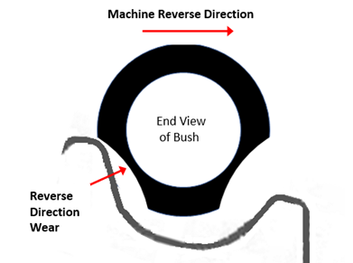
Operating the machine in reverse and under load can cause accelerated wear on the bushes. This form of loading can be caused by: –
- running backwards up an incline
- back blading
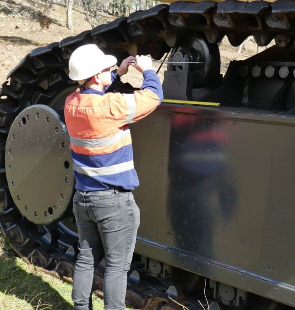
Bushes can be measured using a Calliper, Ultrasonic Tool or Depth Gauge
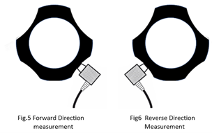
Calliper The wear surfaces should be free of dirt, mud and grime. The wear surfaces should be felt by hand to determine whether the bushes have been turned. If they have been turned, only the Ultra Sonic Tool and the Depth Gauge can be used to measure the wear on the bush. The inspector should then feel by running his hand over the current forward and the reverse wear surfaces to see which surface appears to be most worn. The calliper will then be used to measure each wear surface as shown.
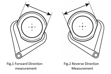
A few measurements should be taken for both the forward direction and then the same for the reverse direction and the worst measurement used for the calculation of worn percentage.
Ultrasonic Tool
Again the surfaces need to be clean of mud and grime, and it may be necessary to use a wire brush to achieve this. The UT tool probe will be applied to the surface will a small amount of Ultrasonic Gel for signal conduction (use high alcohol gel in very cold climates). If a reading is not immediately visible, twist the probe by 90 degrees until a firm consistent reading is obtained. Measure the reverse side and then whichever is the worst reading will be used for the calculation or percent worn. It is good practice to take a number of readings at different spots horizontally as well to determine which is the worst worn area. It is useful to note if the reverse direction is more worn as it indicates heavier wear during reversing operations, and this should be investigated or at least commented.

Turned Pins and Bushes The bush can be turned provided there is sufficient wall thickness (up to at most 75% wear) on the worn faces of the bush. Once the bush has been turned, the wear will occur on the remaining unworn sections of the bush which will look like the following schematic:-
Measuring after a Pin and Bush Turn
The bushes will be measured after a pin and bush turn using the depth gauge or the Ultrasonic Tool only. The calliper cannot be used!
Ultrasonic Tool
The measurement technique is the same as described earlier. The surfaces need to be clean of mud and grime, and it may be necessary to use a wire brush to achieve this. The UT tool probe will be applied to the surface will a small amount of Ultrasonic Gel for signal conduction. Take multiple readings of the current wear surfaces on both forward and reverse sides and use the worst reading for the calculation of percent worn.
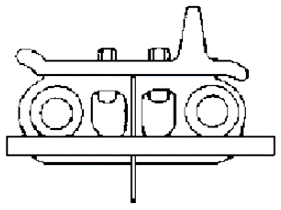
Depth Gauge Measuring
In this case, the manual reading is taken using with the depth gauge placed in the position as shown in the following diagram.
Bush issues and recommended Actions
During the inspection or possibly when the chain is diss-assembled, there could be damage to the pins and bushes. Where there is damage, this should be examined carefully as the metal will tell a story. Here are some pointers to keep a lookout for:-
Leaking Pins
Signs: Signs of dried oil on link assembly. Possible elevated temperature measured with infra-red gun
Possible Causes: Oil has escaped due to overheating or broken/worn out seals
Recommended Actions: Remove and replace dry pins, or refill and reseal.
Pin Spalling
Signs: Chips or flaking material, metal contaminant in bush oil, pin breakage Cracking from oil hole
Possible Causes – Structural fatigue from Shoes being too wide or high impact loads, tight track, inadequate Pin strength
Recommended Actions – replace pins and bushes where required, reduce shoe width, reduce tension on track
Pin Galling
Signs: heavy gouging and scoring on Pin outside Surface
Possible Causes: Lack of clean oil between Pin and Bush, tight track or severe packing
Recommended Actions: Reduce track tension, replace pins and bushes as required
Pin Breakages
Signs: Track Separated, pins broken on diss-assembly
Possible Causes: Tight Track, large amount of packing, heavy impact, incorrect choice of undercarriage for application, incorrect assembly of track.
Recommended Actions: replace pins and bushes where damaged, review undercarriage for the application, remove excessive packing if this is the cause.
Pin End Wear
Signs: Pin wear on ends
Possible Causes: Tight Track, poor track alignment. Worn guides, worn equaliser bar, twister resistor has become worn allowing twisting of front track frame. Idler flange height
Recommended Actions: Cause of wear must be investigated as it may indicate track frame rebuild is necessary. Check condition of guards and whether they need replacement, or extra is required. Check Track tension. Check for interference with Track Rollers